| ► Dimensional inspection of aluminium die cast parts should cover all print-critical dimensions using calibrated gauges or CMM, with Cpk calculation for critical features in first-article and periodic production audits. |
| ► Visual inspection identifies surface defects including flash, cold shuts, misruns, surface porosity (pitting), shrinkage depressions, ejector marks and flow lines — each with a defined acceptance criterion on the drawing or quality plan. |
| ► X-ray inspection (radiographic testing) is the most reliable method for internal porosity detection — porosity above 2 to 3 percent by volume in critical sections is typically unacceptable for structural applications. |
| ► Dimensional checking of machined features (bores, threads, mating faces) requires go/no-go gauges, plug gauges and thread gauges as a minimum; CMM for critical programmes. |
| ► Hardness testing per Brinell (HBW) scale: ADC12 typical range 70 to 100 HBW; A380 typical range 75 to 100 HBW — out-of-range hardness indicates alloy variation or heat treatment issue. |
| ► Weight check: each part number has a nominal weight derived from density and volume; a 3 to 5 percent weight deviation indicates significant wall thickness variation or porosity. |
| ► AQL sampling plan: incoming inspection of die cast parts typically uses AQL 1.0 (critical dimensions) and AQL 2.5 (general dimensions) per IS 2500 or ANSI/ASQ Z1.4 at lot acceptance level. |
INSPECTION METHOD GUIDE
| Defect / Check | Inspection Method | Acceptance Criterion | Frequency |
| Flash | Visual + height gauge | Max 0.3 to 0.5 mm (per drawing) | 100% visual |
| Cold shut | Visual + penetrant test | Zero permissible | 100% visual, periodic PT |
| Misrun (short fill) | Visual | Zero permissible | 100% visual |
| Surface porosity (pitting) | Visual under 100 lux | Per customer standard (typically Ra limit) | 100% visual |
| Internal porosity | X-ray (RT) | < 2% volume per ASTM E505 | Periodic or safety-critical 100% |
| Critical dimensions | CMM or dedicated gauge | Per drawing with Cpk 1.33 | AQL 1.0 sample |
| Threaded features | Thread plug or ring gauge | Go/no-go per ISO tolerance | 100% check |
| Mating face flatness | Surface plate or CMM | Per drawing GD&T | AQL 1.0 sample |
| Hardness | Brinell HBW 2.5/62.5 | ADC12: 70-100 HBW | 1 per lot or heat |
| Weight | Precision scale (0.1 g) | Nominal +/- 5 percent | 10 per lot |
| Metric | Data | Source |
| CMM dimensional repeatability for die casting | +/- 0.01 to 0.02 mm (typical) | Industry practice |
| X-ray porosity detection threshold | 0.5 mm diameter void at 10 mm depth | ASTM E505 |
| AQL 1.0 sample size (lot 500 to 1200) | 80 pieces, 0 defects accept | ANSI/ASQ Z1.4 |
| Flash height acceptance (automotive Tier-1) | 0.1 to 0.3 mm maximum | Customer standard |
| ADC12 Brinell hardness typical range | 70 to 100 HBW | ASTM B85 |
| Shrinkage porosity vs gas porosity identification | Shrinkage: irregular shape; gas: round | Industry practice |
| Die casting dimensional tolerance (commercial) | ISO 8062 CT6 to CT8 | Industry standard |
Why Incoming Inspection of Die Cast Parts Matters
Aluminium die cast parts are precision-engineered components that arrive at OEM and Tier-1 assembly lines as near-net-shape parts ready for assembly or post-machining. Incoming inspection is the quality gate that verifies supplier conformance before parts enter the production flow. Missing a defective batch at incoming inspection can result in assembly line stoppages, non-conforming assemblies reaching end customers or costly field returns. This guide covers every inspection method applicable to aluminium die cast parts and explains what each method detects, how to interpret results and what acceptance criteria to apply.
Visual Inspection: The First and Most Fundamental Check
Visual inspection at 100 percent of incoming parts is the first step. A well-lit inspection station (100 to 300 lux) with a trained inspector detects flash, cold shuts, misruns, surface porosity (pitting), ejector marks, flow lines and packaging damage in seconds per part. The inspector uses a part-specific inspection sheet with photographs of accept/reject examples for each defect type to ensure consistent decision-making.
Flash at the parting line is the most common visual defect. Flash height up to 0.3 mm is acceptable for most industrial applications; automotive exterior and sealing-surface applications require zero flash or flash below 0.1 mm. Flash that exceeds the specification requires rejection or deburring before use. A high flash frequency in an incoming lot indicates tooling wear at the parting face and should trigger a supplier corrective action request.
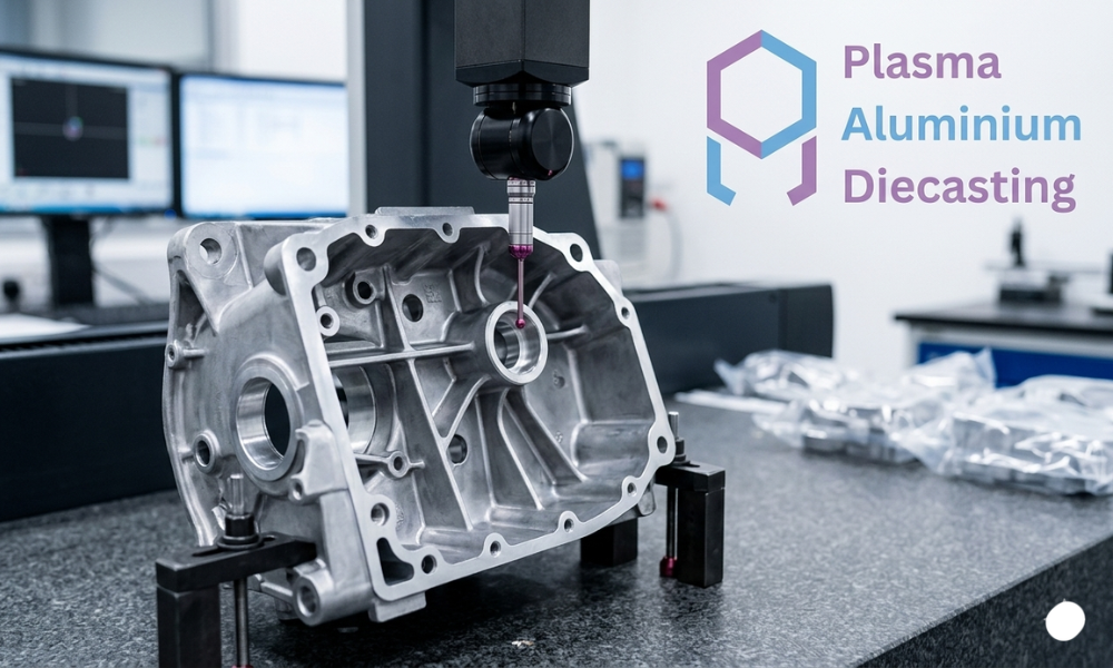
Dimensional Inspection: Gauges and CMM
Dimensional inspection verifies that critical features (bore diameters, mating face profiles, hole positions, overall envelope dimensions) are within the drawing tolerance. For first-article inspection, all print-critical dimensions are measured on a minimum of 5 to 10 parts using calibrated CMM or dedicated gauges. For ongoing production lots, AQL-based sampling is used with a sample size and acceptance number defined by the criticality class of each dimension.
Go/no-go gauges are the most efficient incoming tool for high-frequency dimensional checks on bore diameters and thread features. A gauge set for each part number, maintained and calibrated to the drawing tolerance, allows fast pass/fail checking of each incoming part without relying on variable measurement equipment for every check. Plug gauges for bores, thread plug gauges and ring gauges for threaded features, and snap gauges for shaft diameters are standard.
Surface Defect Classification
Beyond flash, surface defects on aluminium die cast parts include: cold shuts (visible lines on the surface where two metal flows met and did not fully bond — rejectable for structural applications), misruns (incomplete fill at a thin section — rejectable), shrinkage depressions (shallow surface depressions at thick sections caused by volumetric shrinkage — accept/reject based on depth and location), and flow marks (surface texture variation from flow turbulence — cosmetic, accept/reject based on customer standard).
Surface porosity (pitting) is small holes on the cast surface from gas or shrinkage. Acceptance criteria vary by surface function: machined or sealing surfaces require zero porosity above a defined diameter (typically 0.5 to 1.0 mm); cosmetic surfaces use a count and distribution criterion; non-functional hidden surfaces have more permissive acceptance criteria. The inspection plan should specify which surfaces have which criteria.
Internal Porosity: X-Ray Inspection
Internal porosity is not visible on the surface but affects mechanical strength, pressure-tightness and fatigue life. X-ray (radiographic testing, RT) is the standard method for internal porosity detection in aluminium die cast parts. ASTM E505 provides reference radiographs for internal porosity in aluminium castings, classified by type and severity level. Porosity above 2 to 3 percent by volume in critical sections (identified by FEA or customer specification) is typically the rejection threshold.
For pressure-tight castings (hydraulic and pneumatic housings), 100 percent X-ray or pressure testing is specified. For structural parts, periodic X-ray on a defined sample from each production lot (typically 5 to 10 pieces per 500-piece lot) is standard. For non-structural and non-sealing parts, X-ray may be omitted with porosity acceptance based on visual surface criteria only.
Hardness Testing
Brinell hardness testing (HBW 2.5/62.5) on a flat, smooth surface of the casting verifies that the alloy and condition match the specification. ADC12 as-cast should read 70 to 100 HBW; A380 as-cast 75 to 100 HBW. Readings below the minimum may indicate incorrect alloy blend or elevated temperature during pouring. Readings above the maximum may indicate excess iron or copper. One hardness reading per production lot on a retained sample is a reasonable quality plan requirement for non-safety-critical programmes.
FAQ
Q: What is the most common defect found on incoming aluminium die cast parts?
Flash at the parting line is the most frequently encountered defect in incoming inspection of aluminium HPDC parts. It is typically a tooling maintenance issue (parting face wear reducing the sealing contact) and is manageable with periodic die repair. Flash that is within the drawing acceptance criterion is not a rejection; flash exceeding the criterion requires either rejection or deburring.
Q: Do we need X-ray inspection for all die cast parts?
X-ray inspection is mandatory for pressure-tight castings (hydraulic manifolds, pump housings, valve bodies) and is recommended for safety-critical structural castings (suspension components, steering housings). For general industrial and non-structural automotive die castings (brackets, covers, housings without pressure or structural requirements), X-ray is not required unless the customer specification mandates it.
Q: What is the standard ISO tolerance grade for commercial aluminium die casting?
Commercial aluminium die casting dimensions typically conform to ISO 8062 CT6 to CT8 (casting tolerance grades). CT6 to CT7 is achievable for features formed in a single die half or cavity insert without cores; CT8 is more typical for features across the parting line or involving core pins. Machined features after die casting achieve ISO H7/h7 or tighter depending on the machining operation.
Q: How should we record and communicate incoming inspection rejections to Plasma Aluminium Diecasting?
For incoming rejections, the quality contact at Plasma should receive a Non-Conformance Report (NCR) with the lot number, part number, quantity inspected, quantity rejected, defect description and photographs of representative rejected parts. We respond to NCRs within 2 working days with immediate containment action and within 10 working days with a written 8D corrective action report.
Q: What documents should accompany each delivery of die cast parts from Plasma?
Each delivery includes: delivery challan, part numbers and quantities, material test certificate (alloy composition per heat number), dimensional inspection report (for first articles and periodic production audits), PPAP Level 3 documentation (for first articles and post-change deliveries) and Certificate of Conformance signed by quality manager.
Conclusion
Incoming quality inspection of aluminium die cast parts protects assembly operations from defects that originate at the casting source. A comprehensive inspection plan covering visual checks, dimensional verification, surface defect classification, internal porosity assessment and hardness testing addresses every significant failure mode. Plasma Aluminium Diecasting supports its customers with complete PPAP documentation, material certificates and dimensional inspection reports with every first-article delivery and on a periodic basis for production lots. Our quality team is available to discuss inspection plan requirements for new programmes at the enquiry stage.
Contact Plasma Aluminium Diecasting at plasmaaluminiumdiecasting.com contact.
Specifications and pricing vary by order volume, material grade and finish requirements. Contact the team for a detailed technical datasheet and quote.

Prasanna Kumar Tiwari
Plasma Aluminium Diecasting was established after analyzing the worldwide surge in manufacturing demand across diverse sectors — from automobiles to FMCG, Oil & Gas, and Pharma. To meet this growing need, we provide a comprehensive range of precision-engineered products and industrial solutions that streamline production and enhance efficiency. As a Leading Aluminium Die Casting Manufacturer in Pune, our commitment lies in delivering innovative, technology-driven, and cost-effective solutions tailored for modern industries.