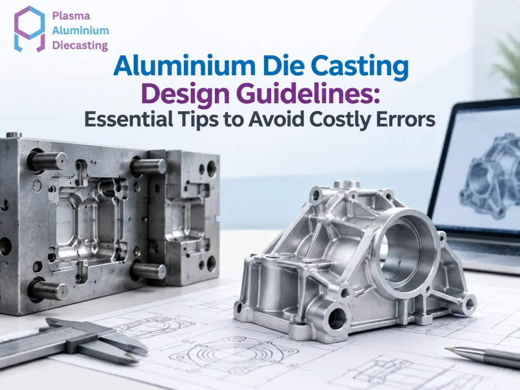
Aluminium die casting design guidelines decide whether your part comes off the production line clean. Skip them, and you risk defects that cost weeks to fix. Most design problems in die casting do not show up during design review. They show up after tooling is already built, when it is far too expensive to change course.
This guide covers the core aluminium die casting design guidelines every engineer should know before finalising a part. Following these aluminium die casting design guidelines early saves both time and money later in production.
Why Aluminium Die Casting Design Guidelines Matter
A part designed without casting in mind often looks fine on paper. But once it reaches the die casting stage, problems surface fast. Uneven wall thickness causes warping. Sharp internal corners create stress points. Poor draft angles make the part stick inside the mould. The North American Die Casting Association publishes detailed design standards covering wall thickness, draft, and tolerance recommendations that most professional foundries reference.
Following proper aluminium die casting design guidelines from the start avoids most of these issues. Good aluminium die casting design guidelines also reduce scrap rates and shorten the time needed to get a stable production run going.
Wall Thickness Guidelines for Aluminium Die Casting
Consistent wall thickness is one of the most important aluminium die casting design guidelines to follow. Aluminium die cast walls typically work best between 2 and 4 millimetres. Thinner walls risk incomplete filling. Thicker walls cool unevenly and can trap gas, leading to porosity.
Sudden changes in wall thickness cause even bigger problems. A thick section next to a thin one cools at different rates. This creates internal stress and, in some cases, visible sink marks on the surface. Designers should aim for gradual transitions between different thickness zones wherever possible.
Draft Angle Requirements in Aluminium Die Casting Design
Draft angle refers to the slight taper added to vertical walls so the part releases cleanly from the mould. Skipping this step is a common mistake among engineers new to aluminium die casting design guidelines. Following the correct aluminium die casting design guidelines for draft angle prevents most ejection problems.
Most aluminium die cast parts need a minimum draft angle of 1 to 2 degrees on external walls. Internal walls or deep cavities often need more, sometimes up to 3 or 5 degrees, depending on the depth and surface texture. Without adequate draft, the part can stick, scratch, or deform during ejection.
Rib and Boss Design Guidelines
Ribs add strength without adding excess material, but they need careful proportioning. A rib thickness of roughly 50 to 70 percent of the adjoining wall thickness usually works well. Ribs that are too thick relative to the wall can create sink marks on the opposite surface.
Bosses, the raised features used for screws or fasteners, follow a similar rule. Keep boss wall thickness proportional to the surrounding structure. This prevents shrinkage marks and keeps the casting dimensionally stable.
Gate and Runner Placement
Where molten metal enters the mould affects how well it fills every section. Poor gate placement leads to incomplete fills, cold shuts, or trapped air pockets. Aluminium die casting design guidelines generally recommend placing gates at the thickest section of the part. This lets metal flow toward thinner areas as it cools.
Runner design also matters. A runner that is too small slows the fill and risks premature solidification. One that is too large wastes material and increases cycle time. Getting this balance right often takes a few design iterations, working closely with the manufacturer’s tooling team.
You can read more about how these considerations connect to actual tooling design through tooling and mould development. This page explains how gate and runner decisions shape the final die design.
Undercuts and Parting Line Considerations
Undercuts are features that prevent a part from being ejected in a straight pull, and they add real cost and complexity to tooling. Wherever possible, aluminium die casting design guidelines recommend eliminating undercuts through redesign. If that is not possible, plan for slides and lifters early rather than discovering the need mid-project.
Parting line placement, where the two halves of the mould meet, also needs early attention. A poorly planned parting line can leave visible flash lines in awkward, hard-to-finish locations, or complicate the ejection process for otherwise simple parts.
Quick Design Checklist Keep wall thickness between 2 and 4mm with gradual transitions. Add 1 to 2 degrees of draft on external walls, more on deep internal features. Keep rib thickness at 50 to 70 percent of adjoining walls. Place gates at the thickest section. Minimise undercuts wherever the design allows.
Dimensional Tolerances in Aluminium Die Casting Design
Tolerance expectations should get set early, not after the first sample parts arrive. Good aluminium die casting design guidelines call for realistic tolerance targets from the start. Standard aluminium die casting typically holds tolerances within plus or minus 0.1 to 0.2 millimetres for smaller dimensions. This varies by part size and complexity. Tighter tolerances usually mean higher tooling cost and more careful process control.
Aluminium die casting design guidelines generally recommend applying tight tolerances only where they genuinely matter for fit or function. Over-specifying tolerances across an entire part adds unnecessary cost without improving how the component actually performs. Reserve tight tolerances for mating surfaces, mounting holes, and other features with real functional requirements.
Surface Finish Considerations During Design
Surface finish requirements affect both the die design and downstream processing. A part that needs a decorative or highly finished surface benefits from a smoother mould cavity finish. Careful attention to gate placement also matters, since gate marks and parting lines can be difficult to fully remove later.
Designers should flag cosmetic surfaces early, since finishing steps like polishing or powder coating work best when the underlying casting quality supports them. Trying to fix a rough or defect-prone surface through finishing alone rarely gives the same result as designing the part correctly from the start.
How Alloy Choice Interacts With Design Decisions
Material selection and part design are not separate decisions. They influence each other directly. Aluminium die casting design guidelines often need adjustment depending on which alloy the project uses. Different alloys shrink, flow, and cool at different rates.
A designer working with a highly fluid alloy can push wall thickness slightly thinner than one using a less fluid grade. Alloy choice also affects how forgiving the design can be around sharp transitions and complex geometry. If you are still finalising which grade fits your application, this guide on choosing the right aluminium alloy helps. It covers how different grades compare across strength, cost, and casting behaviour.
Prototyping and Design Validation Before Full Production
Jumping straight from CAD design to full production tooling carries real risk. Aluminium die casting design guidelines recommend validating critical assumptions through simulation or prototype tooling before committing to a full production run. This matters most for complex or high-volume parts.
Mould flow simulation software can predict where a design might struggle with incomplete fills, trapped air, or excessive shrinkage before any steel gets cut. This step costs time and money upfront, but it costs far less than discovering the same problems after tooling is complete.
Common Design Mistakes That Increase Costs
Ignoring aluminium die casting design guidelines during the early design phase is where most costly mistakes start. Many design problems stem from treating casting as an afterthought rather than a core design constraint. Adding sharp internal corners is one frequent mistake. These act as stress concentrators and increase the risk of cracking. Rounded internal corners, even small ones, distribute stress far more evenly.
Ignoring shrinkage allowance is another common error. Aluminium shrinks as it cools, typically by around 1 percent depending on the alloy. Parts designed without accounting for this often come out slightly undersized, causing fitment issues down the line.
Overlooking symmetry also causes trouble. Asymmetrical parts cool unevenly, which increases the risk of warping. Where function allows, keeping wall sections and mass distribution as balanced as possible helps the part hold its shape through cooling.
How Design Choices Affect Casting Method Selection
The design itself often determines which casting method fits best. Complex, thin-walled parts with tight tolerances typically suit high pressure die casting, since the process fills intricate cavities quickly before the metal cools. Parts that need denser structure and fewer internal defects, like pressure-critical components, often work better with gravity die casting instead.
Getting the design guidelines right early makes this decision easier. A part designed with one method in mind does not always translate cleanly to another. Involving your manufacturer during the design phase, rather than after drawings are finalised, avoids a lot of rework later.
Working With Your Manufacturer Early in Design
The biggest cost savings from following aluminium die casting design guidelines come from involving your manufacturing partner before finalising the design, not after. Experienced manufacturers can flag issues with wall thickness, draft angle, or gate placement long before tooling begins.
This collaborative approach, often called design for manufacturability, catches problems on paper rather than in production. It is far cheaper to change a CAD file than to rework a steel mould that has already been cut.
If you have a part in development, it is worth reaching out to discuss your drawings directly with the engineering team. Getting feedback before finalising the design can prevent costly redesigns once tooling is underway.
Conclusion
Aluminium die casting design guidelines are not just technical formalities. Following these aluminium die casting design guidelines directly determines how smoothly a part moves from design to production, and how much rework you avoid along the way. Getting wall thickness, draft angle, rib design, and gate placement right early saves both time and tooling cost.
Every part is different, and even well-designed components sometimes need small adjustments once real production data comes in. Working with a manufacturer who reviews designs early, rather than only after tooling begins, makes this process far smoother. You can explore the full range of manufacturing capabilities on the Plasma Aluminium Die Casting homepage to see how design support fits into the broader production process.
Frequently Asked Questions
Most aluminium die cast parts work best with wall thickness between 2 and 4 millimetres, with gradual transitions between thicker and thinner sections to avoid warping or porosity.
Draft angle allows the part to release cleanly from the mould without sticking or scratching. Most external walls need a minimum of 1 to 2 degrees, with more required for deeper internal features.
Aluminium typically shrinks by about 1 percent as it cools, depending on the alloy used. Designers need to account for this shrinkage to avoid undersized final parts.
Yes, significantly. Undercuts, inconsistent wall thickness, and poor gate placement often require tooling modifications or additional slides and lifters, which raise both cost and lead time.
As early as possible, ideally before finalising CAD drawings. Manufacturers can flag design issues on paper, which is far cheaper to fix than after tooling has already been built.

Prasanna Kumar Tiwari
Plasma Aluminium Diecasting was established after analyzing the worldwide surge in manufacturing demand across diverse sectors — from automobiles to FMCG, Oil & Gas, and Pharma. To meet this growing need, we provide a comprehensive range of precision-engineered products and industrial solutions that streamline production and enhance efficiency. As a Leading Aluminium Die Casting Manufacturer in Pune, our commitment lies in delivering innovative, technology-driven, and cost-effective solutions tailored for modern industries.